Load
10 N
Design target for the suspended center load.
Lightweight structures case study
Design, simulation, and testing of a lightweight load-bearing structure
This project involved designing, 3D printing, and testing a lightweight lattice structure capable of supporting a 10 N load over a 150 mm square opening while minimizing material usage.
The engineering challenge was not simply making the part strong. The design needed to balance strength, stiffness, mass, manufacturability, and buckling resistance while remaining printable as a single-piece PLA structure.
CAD modeling, ANSYS simulation, iterative redesign, and physical load testing were used together to move from an overbuilt pyramidal frame to a more efficient bridge-like final geometry.
The requirements forced the design away from arbitrary material addition and toward efficient load paths.
Load
Design target for the suspended center load.
Span
Structure bridged a square opening between supports.
Build
Geometry had to print as one continuous lattice.
Members
Minimum member count with identical cross sections.
Section
Common member profile for uniform stiffness behavior.
Objective
Reduce material while maintaining load-bearing capacity.
Lightweight lattices often fail through buckling or manufacturing defects before reaching an ideal material stress limit. The design process treated member layout, member length, and print quality as primary engineering variables.
Tension members primarily carry axial stress, while compression members can fail through instability before material yield.
Euler buckling was treated as the dominant risk, so member length and end conditions mattered as much as stress magnitude.
Reducing unsupported length raised buckling resistance and helped the final design carry load with thinner members.
Round members provided consistent bending stiffness independent of loading direction and were practical to model and print.
Triangular substructures converted the frame into stable load paths instead of relying on flexible rectangular spans.
FDM anisotropy, layer bonding, supports, and local defects were considered because printed PLA does not behave like an ideal solid.
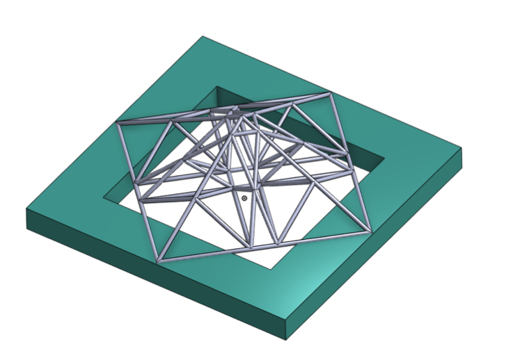
The initial design used a stacked pyramidal structure with 72 members and an estimated mass of about 30 g. It easily carried the design load, but that performance came from excess material rather than an optimized load path.
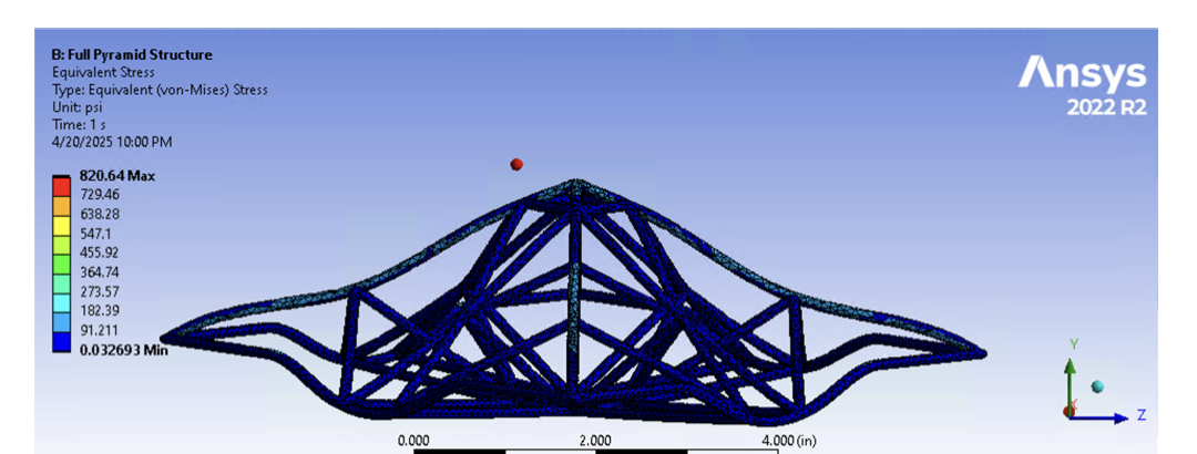
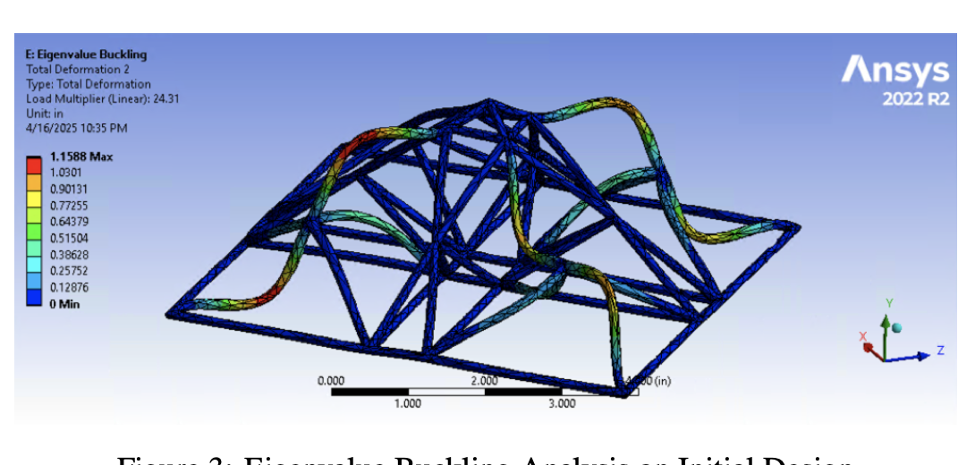
ANSYS results showed a stress safety factor of about 10.77 and an eigenvalue buckling multiplier of about 24. In practical terms, the design was far beyond the required 10 N load case and included many zero-force members that did little structural work.
The second design removed unnecessary members, especially around the base corners, reducing the frame to 48 members and about 21 g.
Stress distribution improved and the stress safety factor dropped to about 1.35, which was much closer to the material-use objective. However, the model still contained zero-force members and left room for additional optimization.
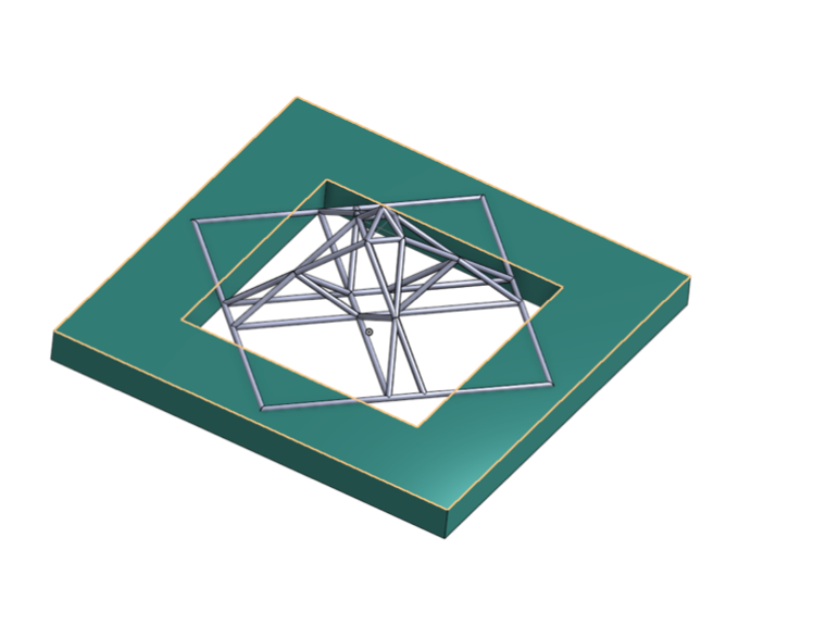
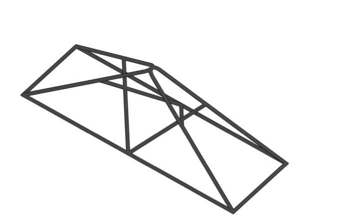
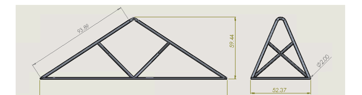
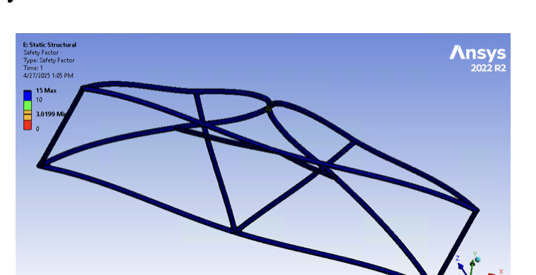
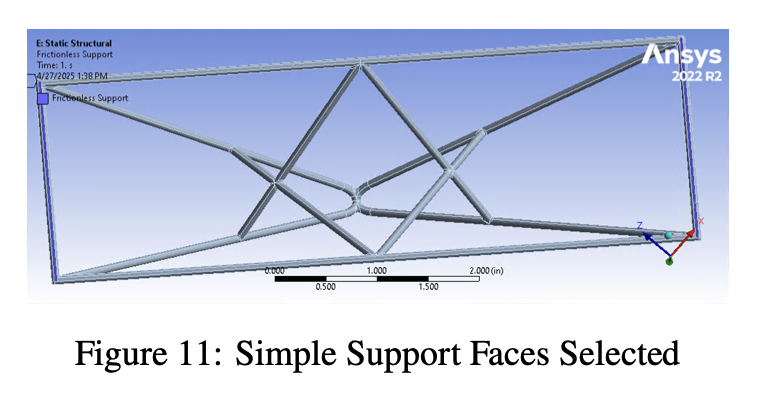
The final design reconfigured the frame to spread stress more evenly while reducing the risk of compression-member buckling. The pyramidal apex was replaced by intersecting bends, and the full perimeter support was replaced with a bridge-like structure that touched two sides of the span.
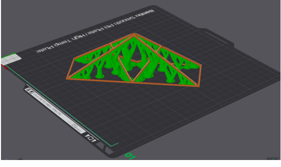
A central opening was maintained for the loading setup. Members were set to a 2 mm circular diameter, which was the smallest practical size for reliable printing on the Bambu Labs P1P while still surviving support removal.
The final model used PLA material properties, mesh refinement, a distributed load at the top, and simple supports at the base faces to represent the table-contact condition.
A
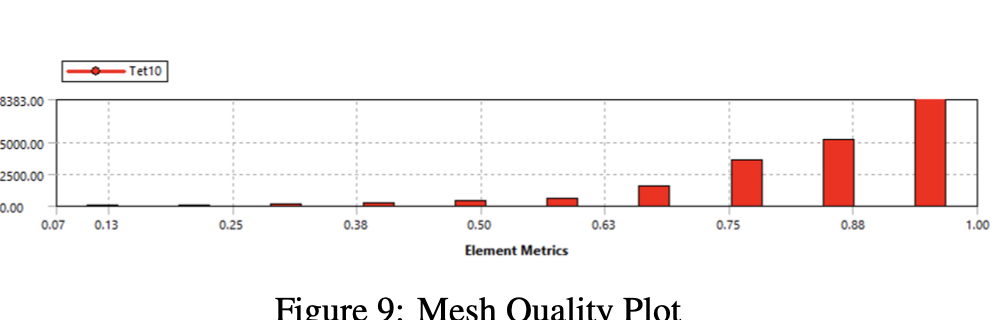
ANSYS Mechanical was used with PLA material properties including an elastic modulus of 3 GPa and Poisson's ratio of 0.35. A refined mesh was applied to the slender members.
The mesh needed enough resolution to capture deformation and buckling behavior without producing a noisy model.
B
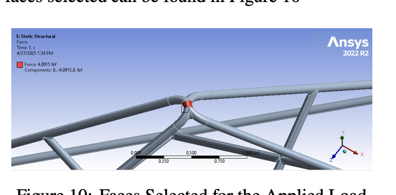
The load was distributed over the upper loading face rather than applied as an ideal point force. The base used simple supports on the contact faces because the structure could slide slightly on the table surfaces.
This better represented the physical test fixture, where force was transferred through the hanging weight setup.
C
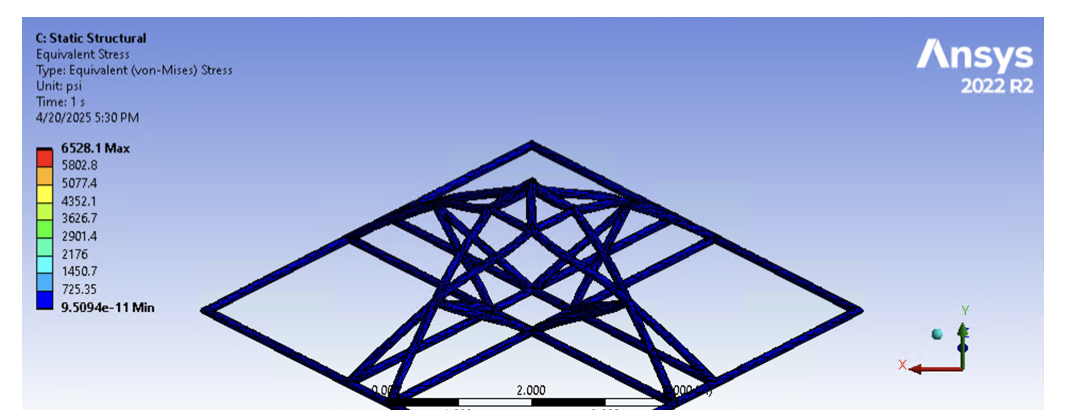
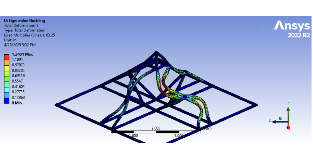
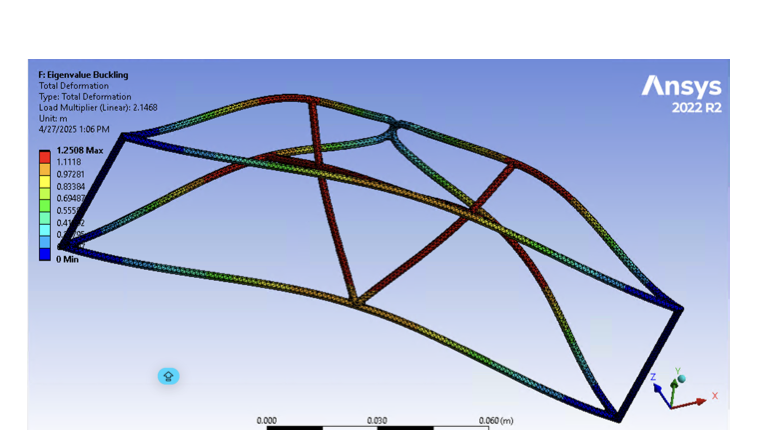
The final design was predicted to safely carry the 10 N design load. The governing simulation result was eigenvalue buckling rather than von Mises stress.
That margin supported moving forward to physical printing and incremental load testing.
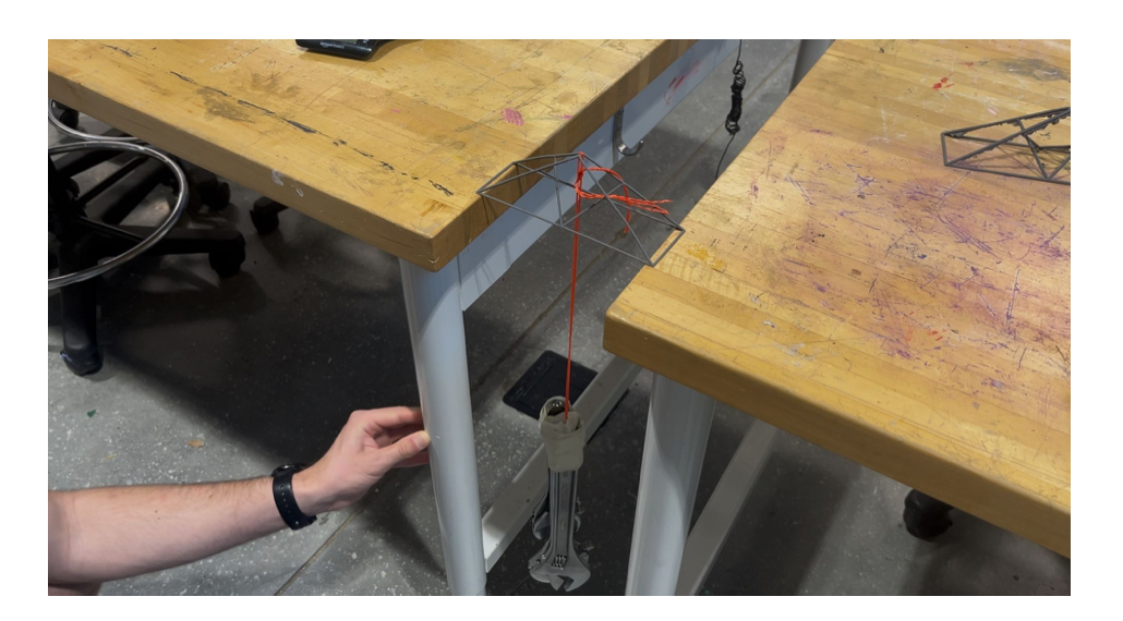
The test setup placed the lattice across a 150 mm gap between two tables. Load was applied through hanging weights attached near the center of the structure, then increased incrementally until failure.
The structure survived 10.01 N and 15.41 N without failure, then failed at about 18.20 N. The first-failure load was estimated near 17.5 N based on the experimental data.
1.748 estimated experimental safety factor
1.136 estimated experimental safety factor
0.962 estimated experimental safety factor
Simulation correctly identified buckling as the controlling failure mode, but the experimental structure failed earlier than the idealized ANSYS model predicted.
The difference was consistent with real additive-manufacturing behavior: the printed part had lower effective infill density, layer anisotropy, small defects from FDM printing, and possible support-removal damage. Those imperfections reduced the strength of slender members and created local stress concentrations.
The final shape required removable supports because the load point sat above the base plane. Support removal became a real design constraint because the same slender members that reduced weight were also vulnerable to handling damage.
Testing and slicer review made 2 mm the practical minimum member diameter. Smaller members improved mass efficiency in theory, but print quality dropped and the risk of cracking during support removal increased.
The final design therefore balanced structural efficiency with the realities of FDM PLA fabrication: anisotropic layer behavior, support scars, infill assumptions, and the need to remove material without damaging the load path.
The final printed structure successfully supported the required 10 N load over the 150 mm span and remained intact through 15.41 N.
Failure occurred at about 18.20 N, validating the core design approach while also showing the importance of accounting for real manufacturing effects in simulation.
For slender printed members, stability can govern before material yield becomes the limiting condition.
Removing inactive members made the design lighter and more meaningful structurally.
Idealized solid PLA does not fully capture infill, layer bonding, support damage, and print defects.
The minimum practical member diameter was set by printability and support removal, not just analysis.
The project moved from a safe but inefficient frame to a lighter bridge-like geometry through repeated CAD, simulation, printing, and testing cycles.
Click any image to open the extracted report asset at full size.