Operating pressure
750 psi
Contain hydrostatic pressure with conservative safety margin.
Mechanical design case study
Design, analysis, machining, and validation of a 750 psi aluminum pressure vessel
This project focused on designing, analyzing, machining, and validating a cylindrical aluminum pressure vessel capable of containing water at 750 psig while holding 50-60 cc of fluid.
The final assembly used a 6061-T6 aluminum body, bored internal cavity, centered 0.25 in NPT threaded port, four-bolt end cap, and static O-ring sealing system. The design emphasized manufacturability on manual machines, reliable sealing, and conservative structural safety margins.
Hand calculations were completed before fabrication to validate hoop stress, O-ring groove sizing, fastener preload, joint stiffness, and separation resistance. Physical testing then confirmed the calculations by pressurizing the completed vessel to 750 psi without leakage.
The constraints favored a simple pressure boundary with a controlled sealing interface and predictable fastener layout.
Operating pressure
Contain hydrostatic pressure with conservative safety margin.
Fluid volume
Hold the specified internal volume while keeping the vessel compact.
Seal
Use a reliable static face seal for pressure containment.
Port
Provide threaded fluid access for testing and filling.
Manufacturing
Keep the geometry practical for a lathe and mill workflow.
Budget
Stay within the material budget for the project.
The final geometry was not the thinnest possible vessel. It was a practical part that could be machined, assembled, and tested repeatedly with acceptable margin.
The first screen check was a thin-wall style hoop stress calculation using the internal pressure, radius, and wall thickness.
The end cap, gland, and O-ring had to work together to hold pressure without leakage or excessive assembly risk.
A cylindrical body reduced turning complexity compared with a flange-heavy concept and made the joint easier to inspect.
The separating force on the end cap was sized against bolt preload, joint stiffness, and separation margin.
The final part was not optimized for minimum mass. It was sized for manufacturability, robustness, and repeatability.
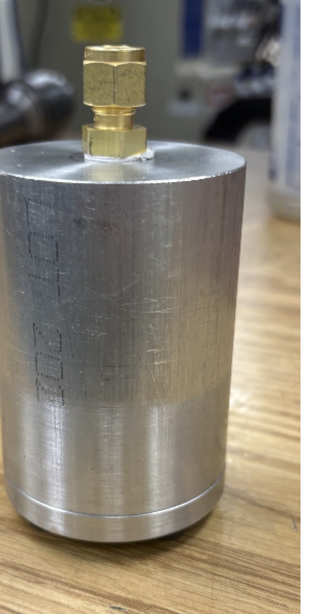
The completed vessel was pressure tested, confirming the analytical and manufacturing decisions in the final design.
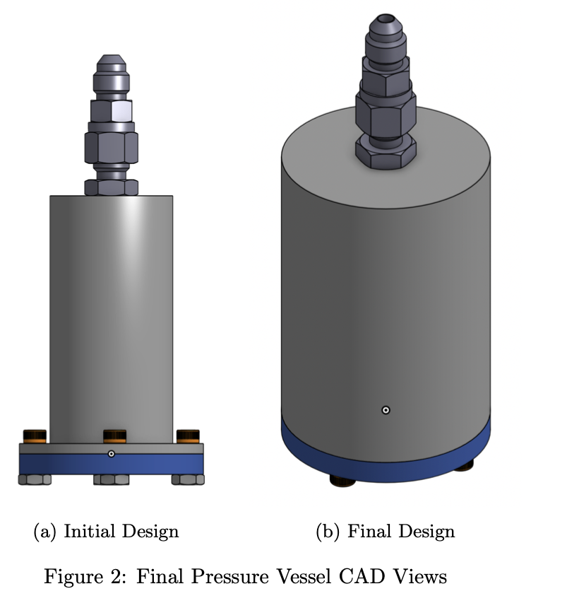
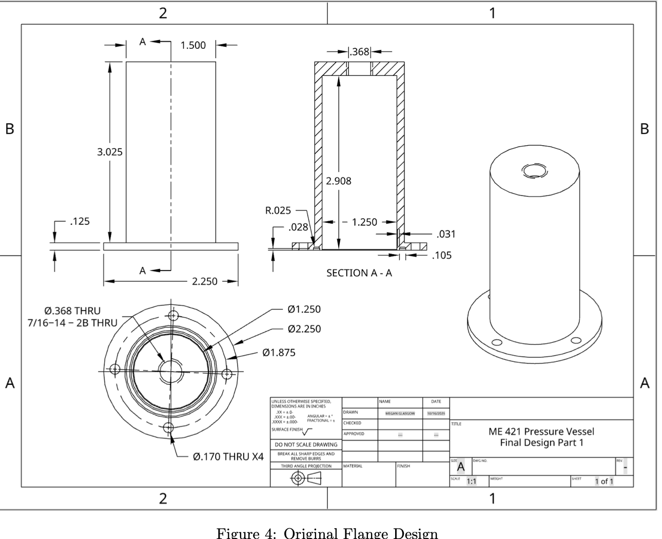
The early design used a flange-based closure with a bolt and nut stack-up. That concept achieved the basic pressure vessel architecture, but it added unnecessary turning operations, more radial material removal, and more setup complexity on manual machines.
The design evolved into a uniform-diameter cylindrical body with threaded holes in the vessel. This removed extra lathe work, reduced the bolt count to four, kept the bolt pattern symmetric, and made the O-ring groove easier to machine between the internal bore and the fastener circle.
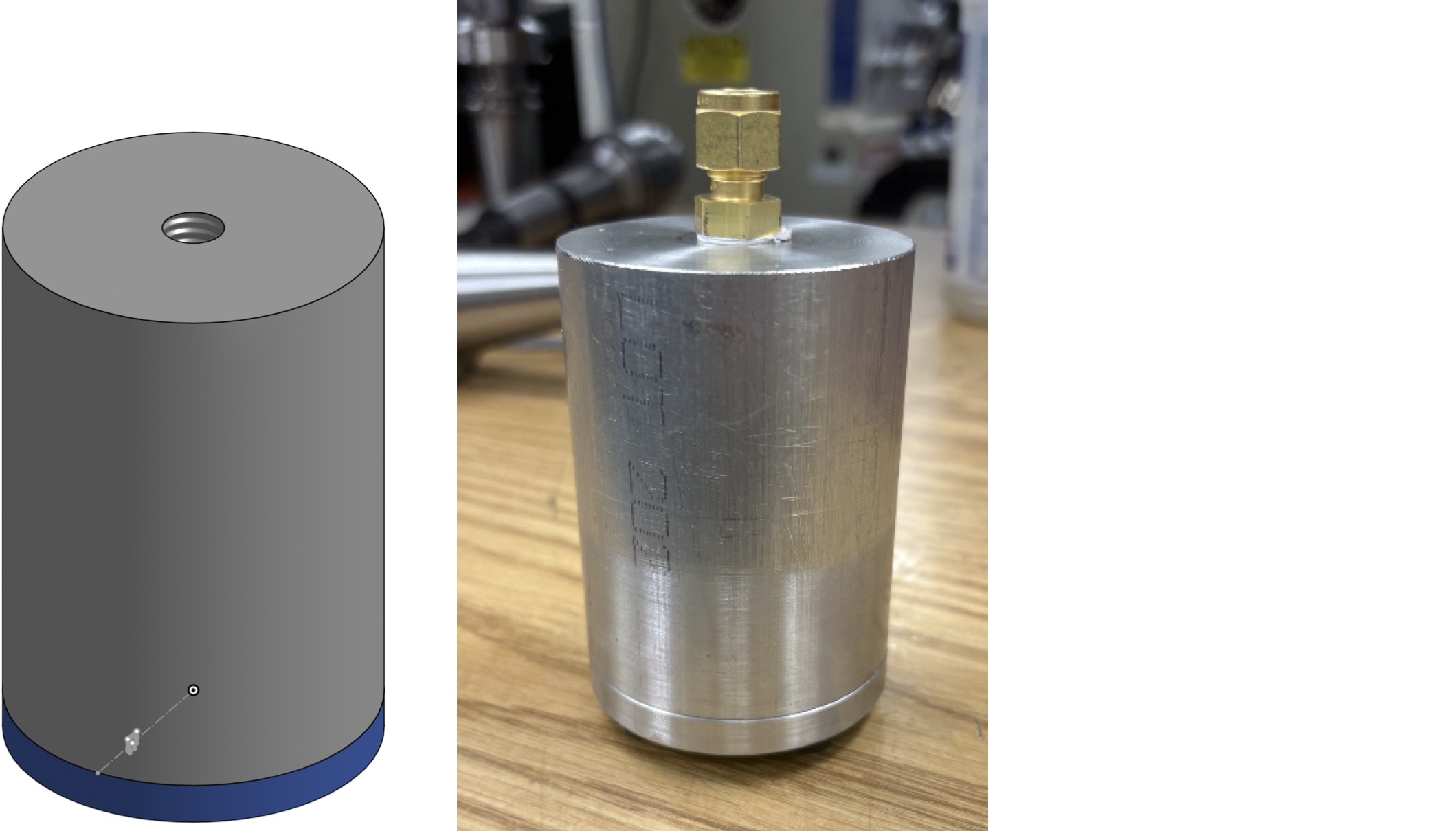
The final vessel was machined from aluminum 6061-T6 stock, selected for strength, machinability, and weight. The body has a 2.500 in outer diameter, 1.250 in inner diameter, 0.625 in wall thickness, and a 2.92 in internal cavity length, giving an internal volume of 3.58 in3, or 58.7 cc.
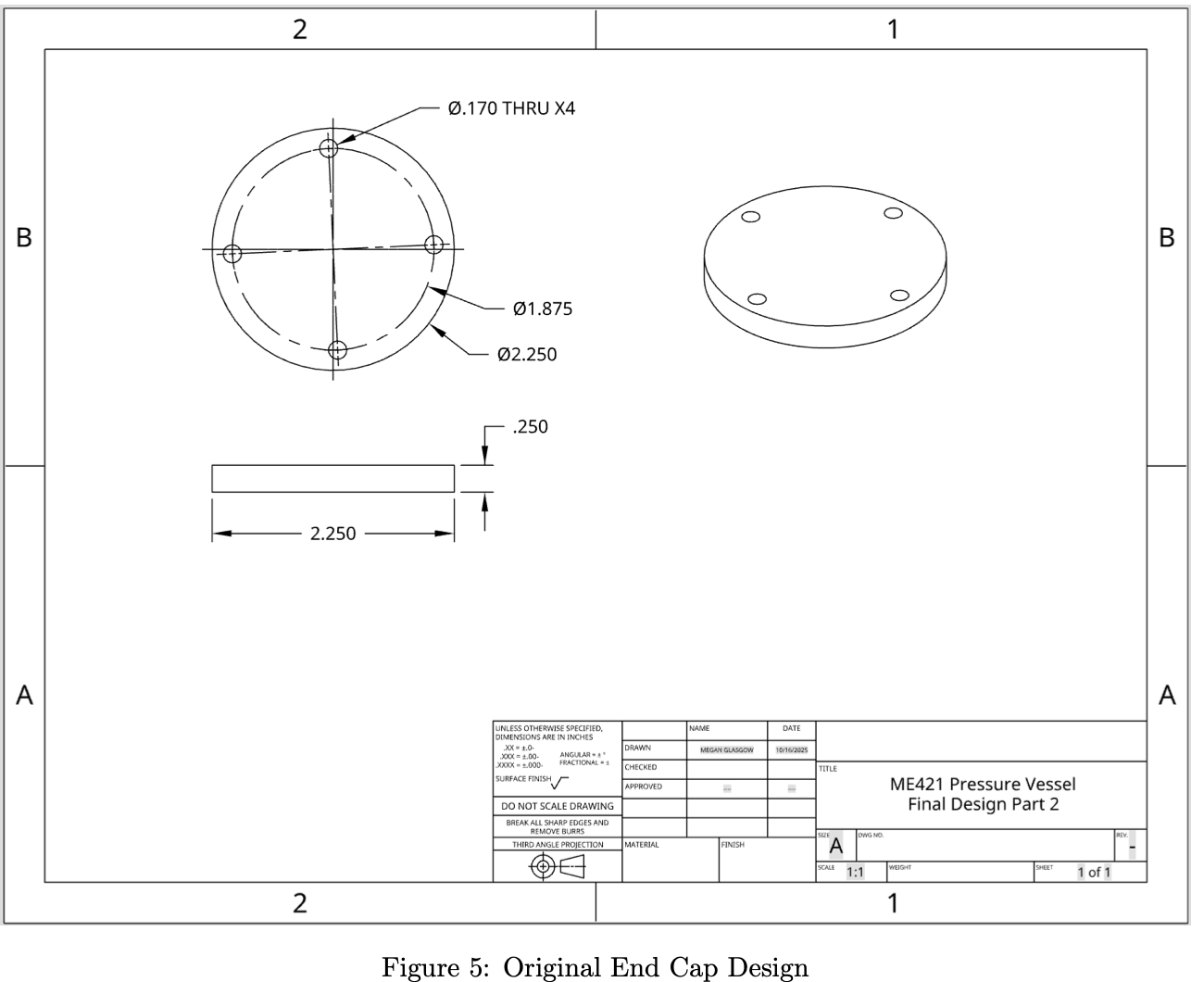
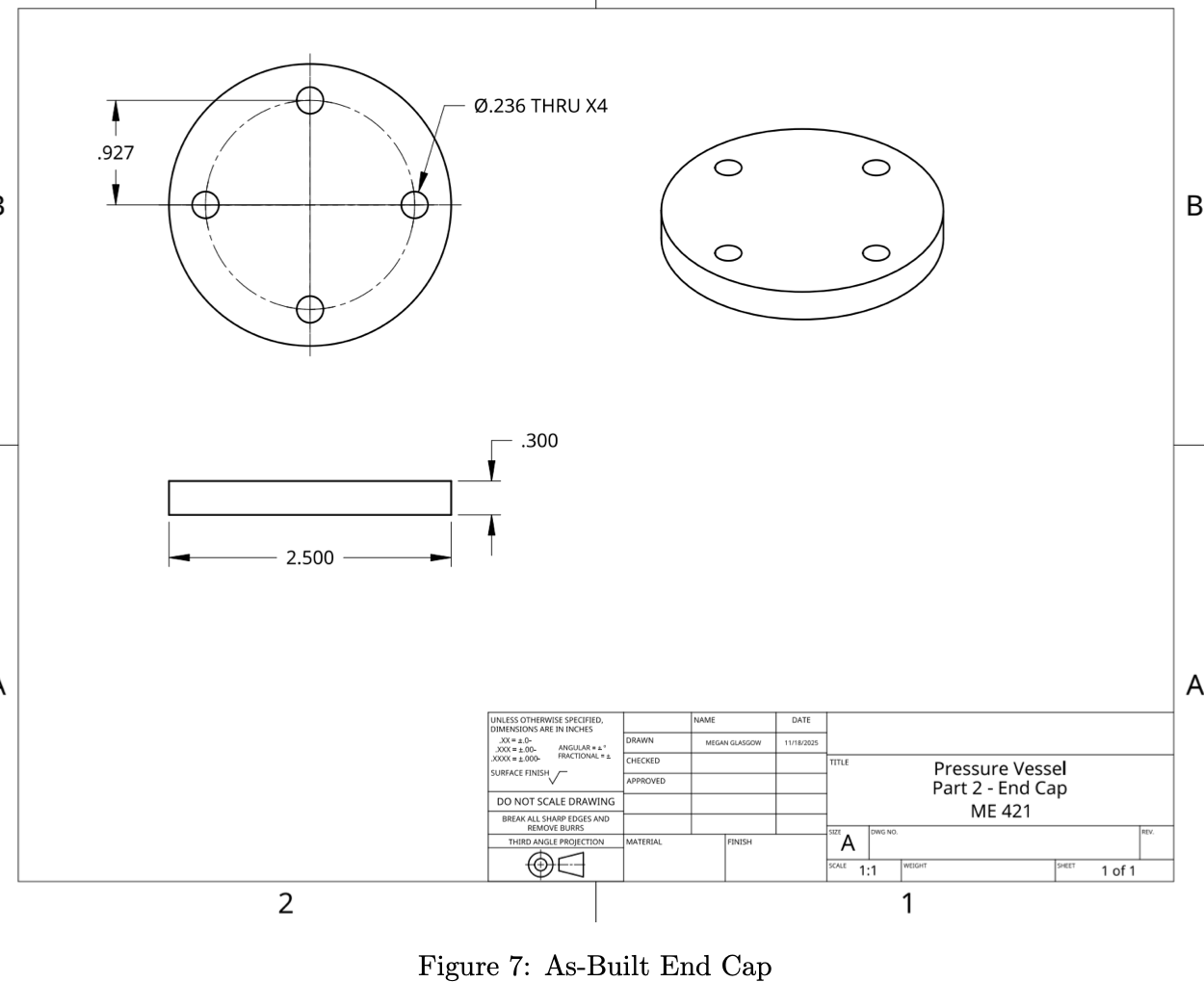
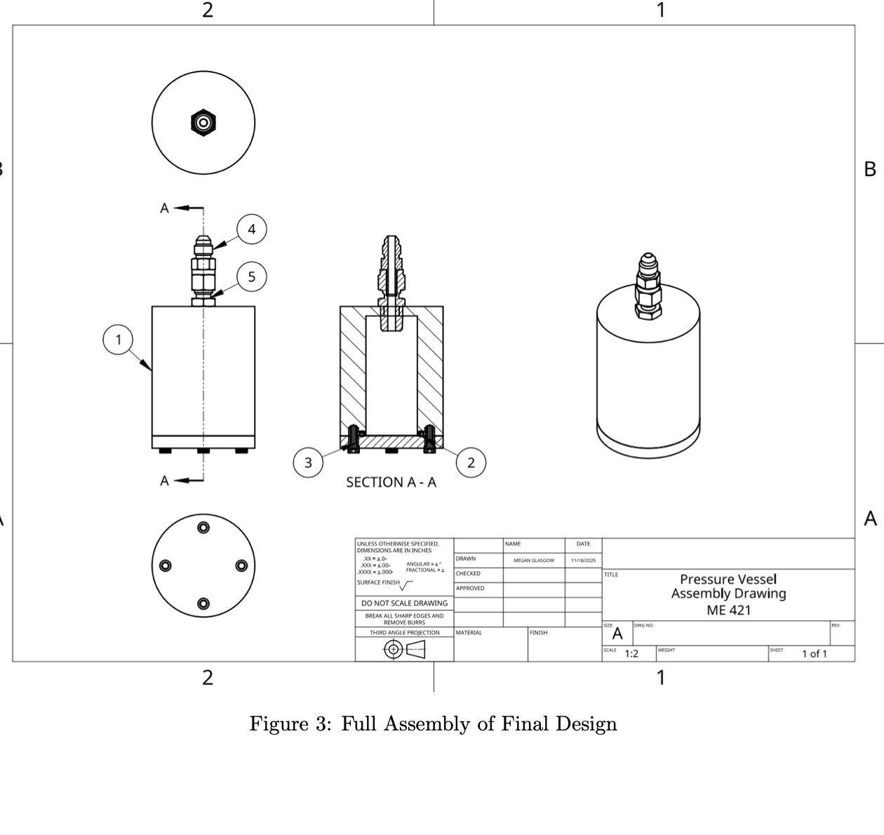
A single 0.25 in NPT port is centered at the top for fluid entry. The end cap sits flush against the vessel body and is clamped by four M6-1 bolts into threaded holes. The O-ring groove sits between the central cavity and bolt pattern, creating a compact static face seal.
The analytical model combined pressure vessel stress checks, O-ring gland sizing, and bolted-joint separation analysis to validate the geometry before machining.
A
Thin-wall pressure vessel theory was used as a conservative screening calculation. With internal pressure P = 750 psi, inner radius ri = 0.625 in, and wall thickness t = 0.625 in, the hoop stress calculation gave sigma_hoop = 750 psi.
Those values produced factors of safety of approximately 53.3 against yield and 66.7 against ultimate failure.
B
The final design used a silicone standard size 219 O-ring because the larger cross section fit between the 1.25 in cavity and bolt pattern while producing a practical gland.
Groove geometry was derived using Parker radial seal design guidance and sized to keep the seal compressed without overfilling the gland.
C
The internal pressure creates a separating force on the end cap that must be resisted by the bolted joint. Using the effective circular area of 1.2217 in2 and design pressure of 750 psi, the total separating force was calculated as 920.38 lbf.
The joint model included bolt stiffness, member stiffness, preload, and torque, with the final stiffness ratio reported as C = 0.0906.
Those factors are intentionally high. The theoretical minimum wall thickness was far smaller, but a thin section would be impractical to machine, more likely to chatter, and less robust during assembly and pressure testing.
The final wall thickness was chosen for manufacturability and repeatable hardware quality as much as pure stress margin.
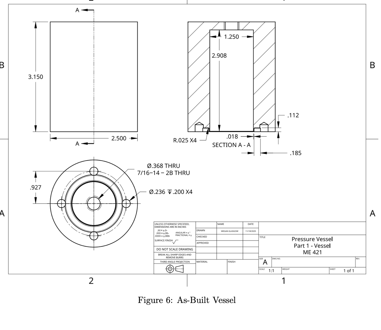
The final geometry was designed around straightforward manual lathe and mill operations. The main lathe work involved preparing the cylindrical stock and boring the internal cavity to the required diameter and depth.
Mill operations focused on drilling and tapping the threaded holes, machining the O-ring groove, and preparing the mating end cap. The simplified cylindrical body removed unnecessary flange turning operations and reduced the number of critical setups.
This manufacturability-driven approach made the pressure vessel easier to machine accurately, easier to assemble, and easier to inspect before testing.
The completed pressure vessel successfully contained pressurized water at 750 psi during testing with no observed leakage. This validated the hand calculations, material selection, O-ring design, fastener design, and manufacturing decisions used throughout the project.
The final design met the project requirements for pressure containment, 50-60 cc capacity, manufacturability, sealing, threaded fluid access, and budget-conscious hardware selection.
The design was simplified so it could be machined, assembled, and inspected reliably on manual equipment.
Pressure containment depends on the full closure system, not just on the vessel wall thickness.
The cylindrical body reduced setup complexity and made the design easier to inspect and build.
The pressure test confirmed that the calculations and fabrication choices worked in the real part.
Click any image to open the extracted report asset at full size.