Parachute-assisted payload delivery and low-velocity airdrop protection
Back to portfolio
Senior Design Capstone
Active Suspension Robot for Drop Impact Mitigation
A reusable active suspension platform designed to reduce peak impact loads during parachute-assisted payload delivery.
Payloads can reach impact speeds near 28.5 ft/s even in controlled drops
Scissor-lift suspension with belt-brake energy dissipation
Reduce peak deceleration through reusable, adaptive impact mitigation
Highlights
Designed a reusable active suspension system as an alternative to single-use passive absorbers such as honeycomb structures and airbags.
Converted vertical impact energy into controlled mechanical motion through a scissor mechanism and belt-brake routing path.
Integrated mechanical design, dynamic modeling, structural analysis, prototyping, and test planning into one working capstone platform.
Why active impact mitigation
Problem Context
The project focused on designing and building an active suspension system capable of mitigating impact forces during drop events. The target application was parachute-assisted payload delivery, where even controlled low-velocity drops can create damaging deceleration loads when the payload reaches the ground.
Existing impact protection systems often use crushable honeycomb structures, foam, or airbags. These solutions can be effective, but they are generally passive, single-use, and tuned for a narrow set of conditions. That limits reusability and makes it difficult to adapt to different payload masses, drop heights, or landing conditions.
Our goal was to develop a reusable, actively controlled system that could respond to impact conditions and reduce the peak force transmitted to the payload.
Mechanical architecture
System Design
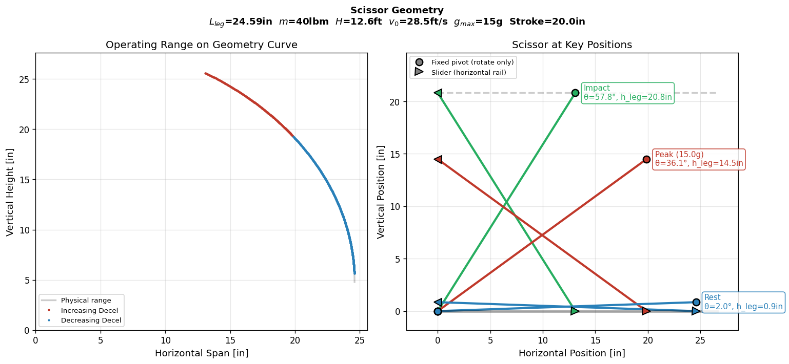
The final prototype uses a scissor-lift style suspension structure to convert vertical impact motion into controlled mechanical travel. The top payload platform moves relative to the lower frame, giving the system stroke distance over which impact energy can be absorbed and dissipated.
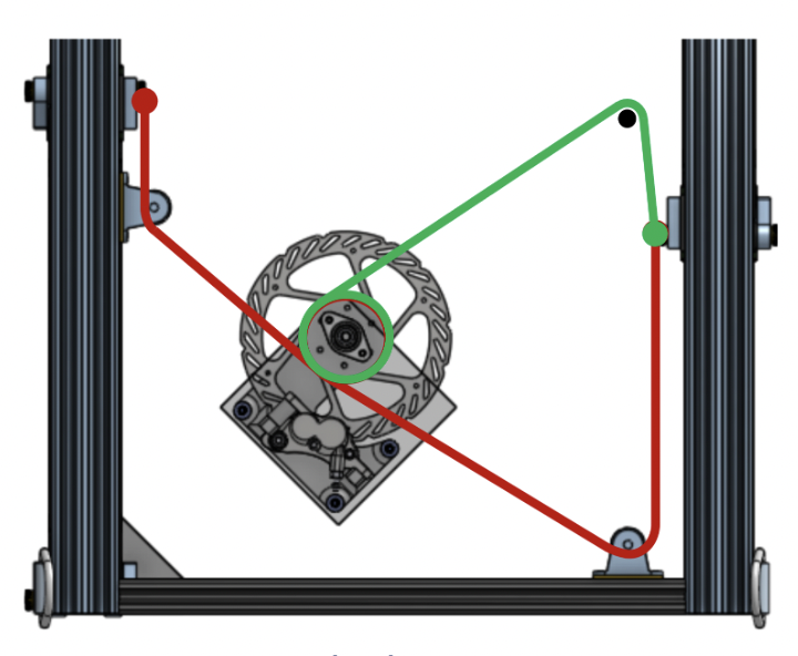
A belt-brake path routes the suspension motion through pulleys and a central braking element. This creates a way to tune resistance during compression, allowing the system to manage impact energy rather than relying only on fixed stiffness. The structure was designed around aluminum extrusion framing, machined brackets, scissor links, bearings, and guided sliding interfaces.
- Suspension geometry provides controlled deformation during impact.
- Frame and linkage layout balance stroke length, stiffness, compactness, and manufacturability.
- Belt routing converts suspension motion into a controllable braking interaction.
- Mechanical stops and structural members protect the platform from overtravel and repeated impact loads.
Modeling before hardware
Engineering Requirements
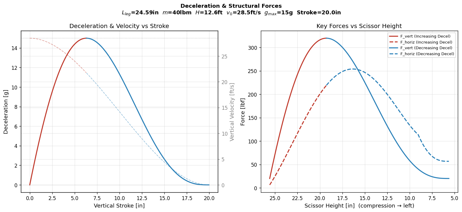
We first characterized the expected drop velocities and impact loads, using the 28.5 ft/s impact speed as a key design case. That analysis helped define the required stroke, energy capacity, structural robustness, and target deceleration reduction.
The system had to reduce peak forces while remaining reusable. That meant designing for repeated impacts rather than one-time crushing. Requirements were framed around controlled energy dissipation, structural survival, repeatable response, and adaptability to different impact scenarios.
- Reduce peak payload deceleration relative to passive impact mitigation.
- Dissipate energy in a controlled and repeatable way.
- Maintain structural integrity under repeated drop events.
- Support tuning through geometry, belt path, damping, and actuation response.
Adaptive response
Active Control Strategy
The active portion of the design was intended to let the system adapt its damping behavior instead of behaving like a fixed passive absorber. During impact, sensing and control components can detect the state of the suspension and adjust the actuation or braking response.
This creates a more flexible design space: the system can be tuned for softer initial engagement, stronger braking as stroke is consumed, or different response profiles depending on payload mass and drop severity. The control strategy connects the mechanical suspension to real-time system behavior.
From CAD to bench hardware
Prototype and Testing
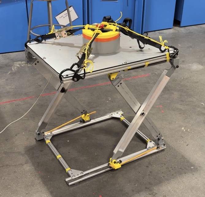
We built a physical prototype to evaluate the suspension architecture under drop-like conditions. The prototype allowed us to check whether the scissor geometry moved cleanly, whether the belt path remained aligned, and whether the frame was stiff enough to support repeated testing.
Testing focused on measuring deceleration forces, validating the system response, and comparing performance against passive baselines. The most important engineering loop was iterative: model the dynamic behavior, build the mechanism, test the response, and refine the geometry and damping assumptions.
What the capstone validated
Results and Takeaways
The final system demonstrated the feasibility of using an active suspension architecture to reduce peak impact forces while remaining reusable. Unlike passive absorbers that are consumed during a drop, this approach can recover after impact and be retuned for new conditions.
The project reinforced that adaptive impact mitigation is a coupled mechanical and controls problem. Mechanical design determines the available stroke, load paths, and energy flow, while sensing and control determine how effectively the system can use that motion during a fast transient event.
- Active systems can outperform passive approaches when the impact condition varies.
- Scissor geometry and belt-brake routing provide a practical way to convert impact motion into controlled energy dissipation.
- Iterative prototyping and testing are essential because real dynamic systems expose friction, compliance, alignment, and timing effects that models alone miss.