Pump load
12.5 lb
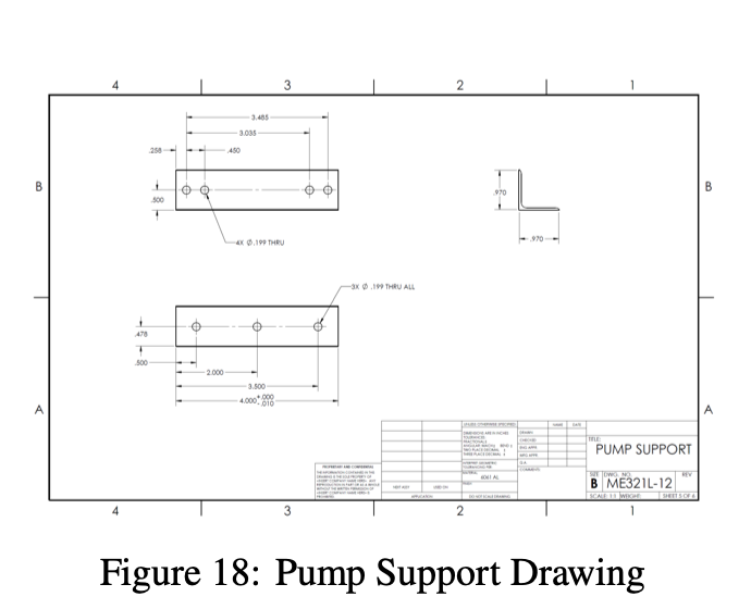
Support the centrifugal pump through its fixed mounting pattern.
Structural design case study
Design, analysis, and prototyping of a structural support system for a centrifugal pump
This project involved designing, analyzing, and prototyping a structural support platform for a centrifugal pump system. The design needed to support combined loading from pump weight, belt-driven pulley forces, and structural reactions, while remaining lightweight, modular, and manufacturable.
The final system was validated through hand calculations, finite element analysis, and physical testing. The finished prototype used an aluminum frame, angled support arms, clevis-pin interfaces, and standard stock geometry to move load from the pump into the surrounding structure.
The engineering focus was to replace excess material with better geometry, simplify fabrication, and confirm that analytical and simulation predictions matched physical performance.
Requirements combined hydraulic performance, structural margins, frame packaging, modular assembly, corrosion resistance, and a strict cost cap.
Pump load
Support the centrifugal pump through its fixed mounting pattern.
Hydraulic target
Deliver flow to a 60 ft head at 65 percent pump efficiency.
Pulley loading
Account for belt forces, pulley torque, and offset reactions.
Deflection target
Limit tip displacement during the design sizing phase.
Safety factor
Meet yield and buckling margins for the critical members.
Height limit
Fit within the available frame and operating envelope.
Assembly
Use removable pin connections for modular installation.
Materials
Use corrosion-resistant standard stock where possible.
Budget
Keep purchased raw material cost within the project cap.
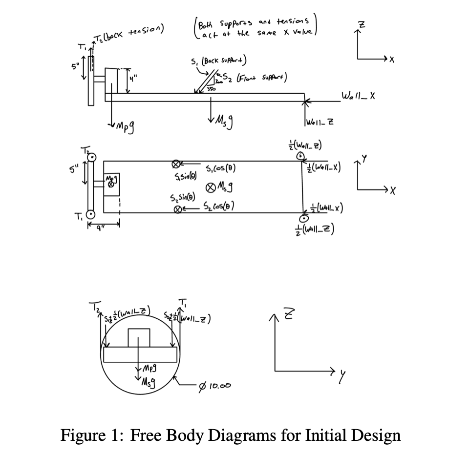
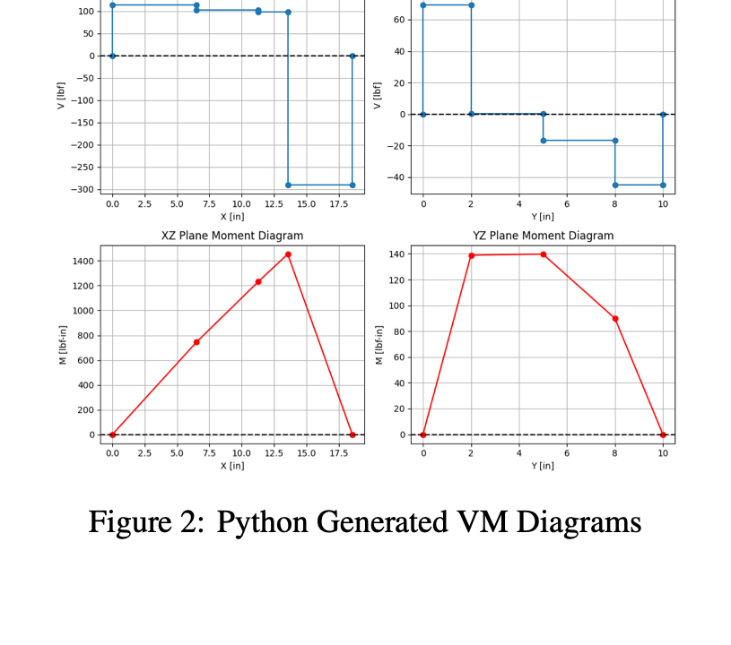
Static equilibrium was used to compute support reactions from the pump weight, belt tensions, pulley torque, and frame constraints. Python was used to solve the reaction system and generate shear and moment diagrams, giving a traceable baseline before simulation.
The platform, support arms, wall mounts, belt tensions, and pump weight were modeled with force and moment balance before detailed stress checks.
The design accounted for belt tension, pulley torque, and the moment generated by the pump-pulley offset from the frame.
Bending, torsion, axial stress, and transverse shear were combined to identify the most demanding stress states.
Through-holes, support-arm pin holes, and platform connections were checked with concentration factors from machine design tables.
Multi-axial stress states were reduced to a single failure metric for ductile aluminum components.
Euler buckling was used to confirm that the slender support arms were stable under compressive reaction loads.
The initial design relied on bulky solid components to resist the pump and pulley load case. That geometry was easy to reason about, but it used material inefficiently and carried load through heavy sections rather than targeted structural shapes.
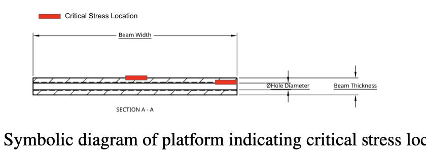
Free-body diagrams were developed to solve reactions at the wall and angled supports. The initial stress model identified critical locations near the platform center, through-holes, and pin connections, where bending, torsion, axial stress, and stress concentration effects combined.
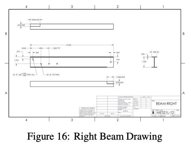
The design shifted from solid, bulky components to a frame-based system using aluminum I-beams, rectangular tubing, and angled members. This reduced unnecessary material while keeping stiffness in the directions that mattered most.
Iteration was driven by both finite element results and practical manufacturing limits. Rather than relying on complex milling, the final architecture used standard stock and simple drilling and reaming operations for the clevis-pin and bolted connections.
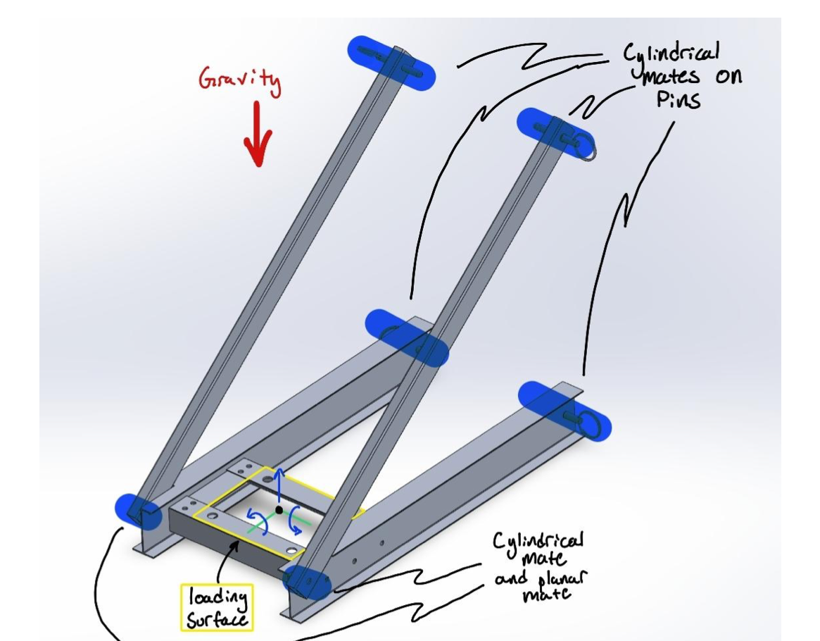
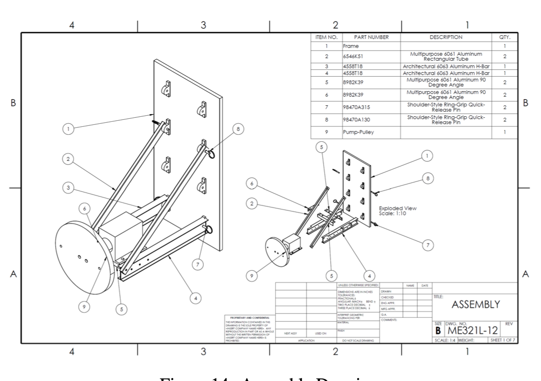
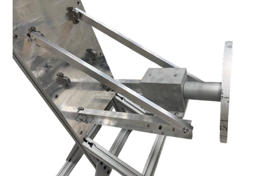
The final design used an aluminum frame structure with I-beams, rectangular tubing, angled supports, and clevis-pin connections. The pump load is carried into the platform, transferred into the support arms, and then reacted by the frame and wall-mounted interfaces.
The clevis pins made the system modular and removable, while the frame geometry allowed high stiffness without requiring a heavy solid platform. The final physical prototype measured 14 in tall, staying well below the 24 in maximum height requirement.
The analytical model combined machine design methods with mechanics of materials. Yielding was checked with von Mises stress, buckling was checked with Euler stability, and deflection was estimated by superposition before comparison against FEA.
A
The pump platform was checked under bending, torsion, axial loading, and transverse shear. Stress concentration factors were applied at holes and interfaces where load entered the structure.
Those locations were carried forward into both hand calculations and simulation review.
B
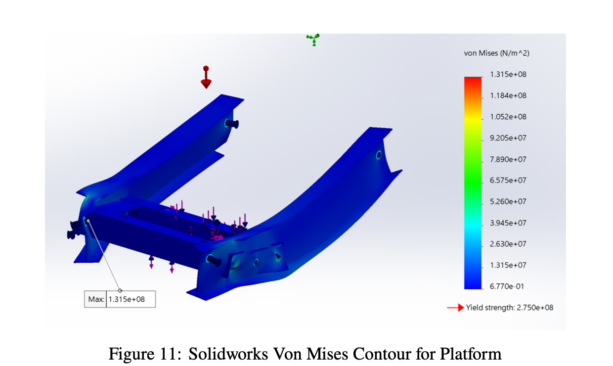
Von Mises stress was used to evaluate yielding in ductile aluminum under combined loading. The platform and support arms remained comfortably above the minimum design margin.
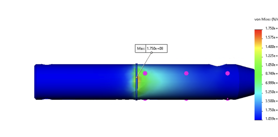
The report also checked pin shear separately because the pins used different material behavior.
C
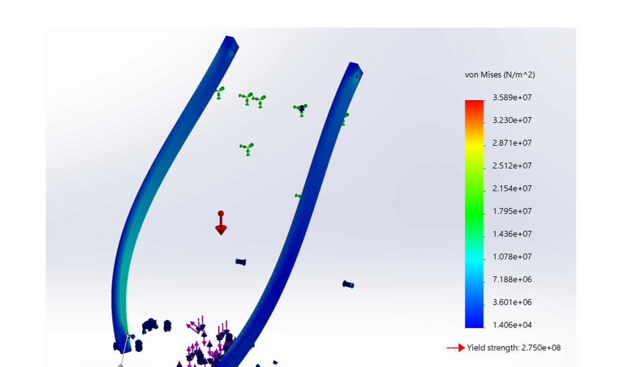
The angled support arms were treated as compression members and evaluated with Euler buckling. Stability margin was much higher than the yield margin.
This confirmed that the final arm geometry was not close to a column instability limit.
D
Deflection was estimated analytically using superposition and then compared against SolidWorks. The initial sizing target was below 1 mm, while the prototype test reported about 2.5 mm under full applied load.
The final measured result remained within the validation allowance documented during physical testing.
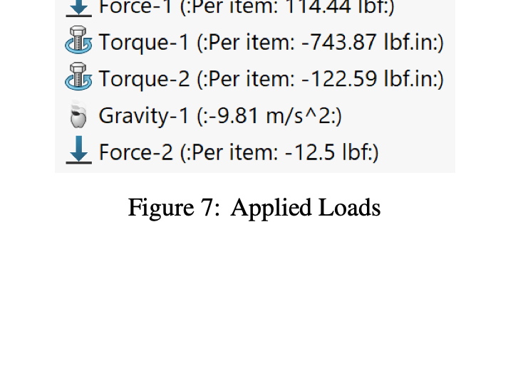
The simulation used simplified loading assumptions, a rigid-body approximation for the pump, and revolute-joint behavior at pin connections. Loads included pump weight, belt force, torque, and gravity.
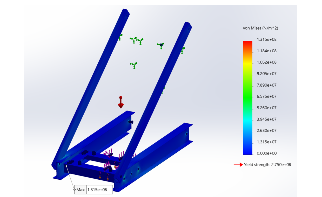
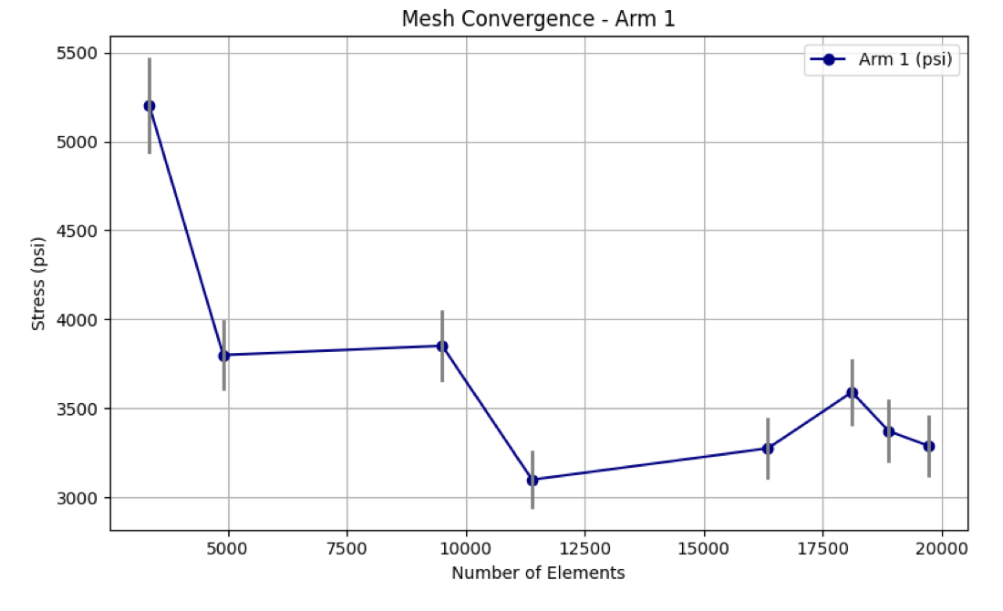
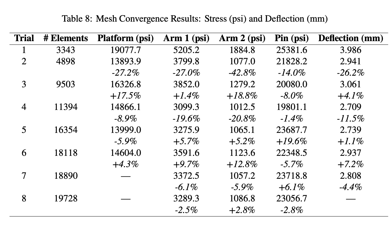
A convergence study refined the mesh until the final stress changes were below about 5 percent. This gave confidence that peak stress trends were driven by the geometry and load path rather than mesh artifacts.
The converged simulation predicted stresses in the support arm, platform, and pin, then compared deflection against analytical calculations and the physical test.
Final mesh von Mises stress for the governing arm region.
Peak platform stress near the top cross section and connections.
Highest localized stress, checked separately against steel pin capacity.
SolidWorks prediction compared with the analytical estimate of 2.441 mm.
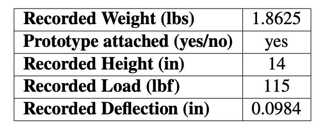
The final prototype successfully supported the applied load without visible structural failure. The measured deflection was about 2.5 mm under 115 lbf, and the report documented this as within the validation limit used during physical testing.
SolidWorks predicted 2.807 mm of deflection, while the hand calculation predicted 2.441 mm. The simulation and experiment aligned within about 20 percent, supporting the combined analytical and FEA modeling approach.
Measured prototype mass during validation.
Final assembly remained under the 24 in height limit.
Full applied validation load on the physical prototype.
Equivalent to about 2.5 mm during testing.
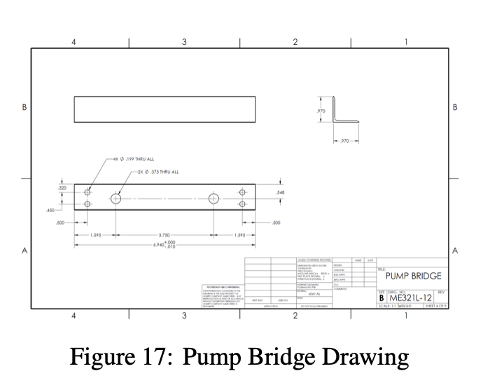
The fabrication workflow relied on standard aluminum I-beams, rectangular tubes, angle sections, and simple drilled or reamed holes. This reduced shop time and avoided the complex machining that the heavier early concept would have required.
Clevis-pin connections made the support arms removable and simplified assembly. Bolted and pinned interfaces also made it easier to inspect, fit, and adjust the prototype during frame installation.
During fit-up, minor interference between the support arms and frame was resolved by carefully filing the top corner of the affected arms. The adjustment removed minimal material and did not change the validated structural load path.
The prototype carried the validation load, stayed within the height limit, and produced measured deflection close to the analytical and FEA predictions.
The final design confirmed that structural efficiency came from better load paths and standard section geometry, not from simply adding more material.
The frame-based design maintained strength with I-beams, tubing, and angled supports instead of relying on bulky solid material.
Pump weight, belt forces, pulley torque, and support reactions created a multi-axis load case that required a clear equilibrium model.
The simulation predicted realistic trends, but the physical test was needed to confirm deflection and full assembly behavior.
Standard stock, simple holes, and modular pins reduced fabrication risk and made the prototype more practical.
Moving from a heavy initial concept to a lighter frame structure improved stiffness-to-weight behavior while keeping the design under the project material budget.
Click any image to open the extracted report asset at full size.